AH-64D TEDAC FOR DCS
Last updated: December 24th, 2024
Build instructions
Youtube build series
GRIPS
First print hannibal's grips, except for the hat sections. You will need to print the original file + a mirrored version, to have both sides grips.
Then print the hat sections, spacer and trigger assembly from my thingiverse.
We'll start with all the buttons and switches in the different sections of the grips first, and finish with the hat sections.
For each non-hat section you will need 4 x 12mm pushbuttons, one 3-position momentary rocker switch and one trigger assembly (which requires one mini limit switch, one 6x6x4.3 switch and a 19x7 mm aprox spring:


We can start by building the trigger assembly and move it aside. Use piano (1.5 mm) wire to align it and glue it together:

Out of the 4 legs of the 6x6 buttons, two of them are connected together. You need to solder one lead to each pair of legs. The limit switches have a common leg (C), a normally open (NO) and a normally closed (NC) ones:

You need to solder one lead to the common leg, and the other to the normally open (NO) leg. I held both buttons with a dab of superglue once the leads were soldered.
You can now start assembling the grips, except for the top hat part. First glue the spacer to the inner part of the grip, you can use a screwdriver or a barbecue stick to align the holes:

Now add all the buttons and switches required for the bottom part of the grips (four 12mm pushbuttons, and a MOM-OFF-MOM rocker switch), and put the trigger assembly in place. Then solder one long wire to one leg of each button and the center pin of the rocker switch as per the below image (sorry for the use of the black wire on black background):

Then solder one individual wire for each remainging left. Consider the lenght of the wire as it needs to reach the top of the grip:

You can now screw the two halves together, that is the big side piece with the two other small pieces. You should end up with one common wire, in my example the black wire, and eight individual wires, in my case yellow. The below picture shows the right hand grip instead, which I chose red for:

Besides several M3 12mm and 16mm screews, you will also need an M4x50 and an M4x70 long screws
The TEDAC has about 80 digital inputs, and there aren't that many pins in an Arduino Pro Micro (it only has 14 digital and 4 analog pins*), so we are going to need some way to get more inputs, and there are many ways to achieve this, but we are going to work with 3:
-
A button matrix: not going to go too much into detail, you can google that yourself, but essentially buttons are connected in a matrix of rows and columns. The buttons in the TDU PCB are connected this way, in a 3 x 7 matrix, so you will see them labeled as R1, R2 and R3, and C1 to C7 in V2.0 of the PCB. The downside to this method is that unless you include diodes in each crossing between rows and columns, you may have ghosting issues if you press more than one button at the same time (random other inputs of the matrix are registered). Since you are not supposed to press multiple buttons at the same time in the TDU anyway, the PCB design does not account for those diodes. V2.1 version of the PCB is designed to use shift registers instead, which gets rid of that problem anyway.
-
I2C I/O port expanders: this boards connect via I2C protocol to the Arduino and add 16 digital inputs/outputs using only 4 pins of the Arduino. Moreover, you can daisy chain up to 8 of them, providing up to 128 extra pins. For this project, you only need 4 of them, 6 if you plan on using V2.1 TDU PCB with this system. I've only accounted for two build methods in this tutorial, so if you wish to use this method, I'd recommend you use V2.0 instead and just the 4 port expanders.
-
Shift registers: this is my recommended method for this build process. These chips allow for for 8 extra digital inputs, so you will need twice as many for this project, and connect to the Arduino via 5 pins, but they are very inexpensive, reliable, and compatible with MMJoy2, which is the software that we'll use to program the controller. If you chose to build yours with the I2C port expanders, you will need to upload the sketch that I programmed via the Arduino IDE, and it requires a bit more fiddling with coding. You can use either V2.0 or V2.1 TDU PCB for this method.
The picture below shows how I have connected the first 8 wires + the common one to the first shift register input pins:
*You can actually use all 18 pins as digital inputs, or use 5 of some of the digital pins as analog inputs for a total of 9 analog pins and 9 digital pins, but the mentioned combination of 14 and 4 is the one we are going to need for this project

I've used a custom made PCB in this build. This board pulls the pins up via a 10k resistor and when a button is pressed, the pin is pulled down to ground (black wire is connected to a ground pad).
The picture shows a second shift register PCB attached to the first one as these can also daisy chain up to 8. Left grip requires 4 of these boards and right grip requires 3 + 1 extra that will be stored in the enclosure.
If you chose to use the I2C port expander boards, the process would be the same, only you would need only two boards for each grip and at this step you'd have one board with only 8 of the 16 pins soldered. The other 24 pins will be soldered in the other half of this board and the new one. Remember that if you use the I2C boards, you'll need to set a different I2C address for each one of them by connecting pins A0, A1 and A2 to VCC. When using these, my suggestion is:
-
Leave one board as is, without connecting anything. This will be address 0x20
-
Connect A0 to VCC in one board: This will be address 0x21
-
Connect A1 to VCC in one board: This will be address 0x22
-
Connect A2 to VCC in one board: This will be address 0x24
Let's address the elephant in the room when it comes to shift registers available in the market. 74HC165 shift registers can be readily found in 3 formats, each one with its own challenges:
-
As the single chip itself: in this case you would need a breadboard to be able to connect the pins and add any components necessary for its proper function (resistors, capacitors...). I made a custom made PCB with the pins pulled up to VCC. You can find the gerber file in the files section, but you will need to source and assemble small SMD components, which can be challenging sometimes
-
3 in 1 breakboards: as its name suggests, this breakboard contains 3 shift registers in one board, so it's a 24 pin expansion board (click here to see a picture). But what if the quantity doesn't fit our purpose? Let's see our project as an example. The right grip has 23 digital inputs, which makes this board a very good option. However, the left grip has 32 inputs, so we would need 4 shift registers. Using this board, we would be missing 8 pins, so you would need to use one more board. I still think these boards are the best option, but this means that instead of just 5 wires coming out of the left grip, you would need to also get the 8 missing wires out to a board inside the enclosure. And you will have a lot of unused pins which feels a bit of a waste.
-
Individual breakboards: single chip breakboardscan be found in the market (click here to see a picture). However, for some reason, manufacturers decided it was a good idea to leave the expansion pins floating, meaning they are neither connected via a resistor to VCC nor ground. My guess is that this is done to allow the user to chose between pulling up or down the pins, or maybe to save some cents on the resistors. However, I believe it would have been much better to just add resistors and pull them up or down. Both ways work just the same. With these boards, you will need to add the pull up or down resistors yourself. It would be something like this:
.png)
Then the buttons would be connected one leg to VCC (the common one) and the other to each one to pins A to H.
*Note: if you connect the bottom end to the resistors to VCC instead, and then the common wire to GND, that would be a pulled up pin. Both ways work the same, but bear in mind that whether you use the I2C or my custom made shift register PCB, you need to connect the common wire to ground, not VCC.
With the bottom part of both grips finished, you can start building the hat part. Start by adding all the buttons and switches to the proper spots. Use M2 or M2.3 small screws to attach the 4 way hat switches and the right hand grip joystick. I would recommend not to attach the FCR and TADS FOV hat switches until the wires have been soldered to them, as they are recessed in the part, and then again, solder a wire through each one of the switches/buttons, except for the 6x6x15 one in the bottom. That one will require two individual wires. You will see why in a minute:


And once again, solder one individual lead to the rest of the pins:

A rat's nest
Now solder 16 of the wires to two new shift registers (or one I2C port expander). You'll end up with 9 loose wires (7 from the top section + 2 from the 6x6x15 button in the bottom). You can now connect the two sets of shift registers together, bearing in mind that there's a direction (there's an IN and an OUT, and the last out of a series of shift registers is the one that will be connected to the Arduino):

Notice the long leads to the left. Those are the ones that will be fed into the enclosure.

You'll need to feed the 6x6x15 button wires where the previous wires were, as seen in the above picture. That's the reason you couldn't solder those earlier.
The right hand grip is pretty much the same, with one slight difference. It contains the analog XY joystick, which requires two analog wires, ground and VCC:

Fortunately, you can just use the same VCC and ground that the shift registers use, so you don't need to feed those wires to the interior of the enclosure, only the two analog ones.
You can now feed the wires coming out of the last shift register into the enclosure and close them (Pro tip: close it with just one or two screws for now. You don't want to test it, have something fail and have to unscrew a handful of screws to open up the grip for troubleshooting. Don't ask me how I know).


Quick reminder, at this point you should at least have the following wires coming into the enclosure:
-
Red and black: VCC and GND
-
Blue: Clock (also known as SDK in I2C port expanders)
-
Yellow: Data (also known as MISO, serial out, SDA...)
-
White: Parallel load, only on shift registers (also known as latch, SH/LD, CS...)
-
2 x Green: Analog outputs for X and Y axis (only right grip)
You'll need at the bare minimum 3 additional digital pins for the DAY/NT/OFF switch. If you used I2C port expanders, you should have 9 available pins in one of the two right grip ones (the right grip has 23 digital inputs and each port expander has 16 pins, so a total of 32). You can then use 3 of those available pins and feed the wires to the enclosure to connect the switch.
If you used shift registers, you'll need 3 of them in the right grip, but that'll leave you with only one pin left, so you'll need a fourth shift register just for that switch. In that case, the wires coming out of the grip will have to connect to that fourth shift register and then to the arduino. You can kind of see that in the above right picture.
Here's a simple schematic of how wires are to be connected to the arduino at this point (option with shift registers):

If you are using port expanders, VCC and GND are the same, but SDA connects to pin 2 and SCK to pin 3.
Note: the below section will be completed with more detail and pictures in the near future, as I don't have any available at the moment, but I'll try to give at least basic instructions so you can finish your project.
TDU
For the TDU, you'll need to get the PCB available in the files section (for now, the recommended version is 2.0 as it will work perfectly fine with any of the two methods. Contact me if you want to ask me anything about V2.1 anyway).
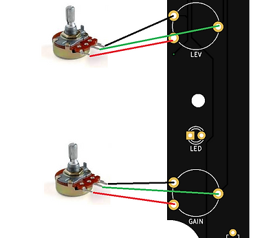
If you don't need the back lighting, the only thing you'll need to solder to the PCB are the 6x6x7 pushbuttons (there are 21 of them), and leads for the two potentiometers. There's also marks in the PCB for soldering 2.54 JST XH connectors, but you can solder wires directly into them instead. Buttons and potentiometers go on the front side of the PCB (obviously), but wires need to come out from the back side.
The pots need to be soldered with 3 short wires (a couple of inches/5 cm should be enough) to the board as such:
The connectors on the back of the PCB are labeled as:
-
+12V/GND: only needed to power the backlight leds
-
B/R/A1/A0: these is the pots connector. B stands for black (GND), R for red (VCC) and A1/A0 are the signal pins (which we will actually connect to pins A2 and A3, don't worry too much about which one goes where)
-
R1 to R3 and C1 to C7: these are the rows and columns pins for the button matrix
Besides that, the PCB has a hole where the DAY/NT/OFF switch is located. You can use an SR16 or an RS1010 swtich for this. They usually have a common pin and individual pins for each position (they are essentially 3 push buttons put together and sharing one leg:

The above image is just for reference. Make sure you double-check with a multimeter which are the 1, 2, 3 pins that are connected with each position of the switch.
The TDU is to be connected to the Arduino board following the below schematic:

BACKLIGHT (optional)
Backlight on the TDU is obviously optional, and it's only intended for aesthetic purposes. If you decide to build your unit with backlight included, you will need to solder 9 (nine) 6x6x7 pushbuttons with green leds + 9 (nine) 3mm individual green leds + 6 (six) 220 ohm resistors. You will also need to power them. You can either use a banana plug inserted somewhere in the back of the enclosure, to plug in a 12V power supply, or if you will be building your unit with an LCD, you can connect the backlight power to the LCD control board, as these use 12V as well. See picture below:

Leads can be soldered to the power in connector of the lcd screen mainboard. These in turn can be connected directly to the VIN and GND pads of the MPD PCB, which would turn the backlight permanently while the TEDAC is plugged in, or use a switch in between to turn them on and off.
FIRMWARE
The firmware is essentially an Arduino sketch that needs to be loaded into the Arduino Pro Micro for it to work as expected. The sketch is in the Files section. However, if you upload it as is, Windows will detect the device as an Arduino Pro Micro. You'd be fine just like that, but if you were to have other Arduino devices plugged into the computer, it could get confusing. I have a DIY collective which also uses an Arduino Pro Micro, so when I went to bind the controls, I would find two Arduino Pro Micros and I would need to be very clear on which one is which.
To solve that problem (and also have a cooler device), you can download and save the hardware folder, also in the Files section, and save it in your Documents/Arduino/hardware folder (create the folder if it doesn't exist).
That is essentially a folder that renames the Arduino Pro Micro but keeps everything the same, so when uploading the sketch, instead of selecting that board, the below one is available:

The device is now an Apache TEDAC in all effects:
